Talk:New tie paradigm
Sprotiel, I think you're confusing the way in which drag forces are computed in the general case. That is, your equations probably work fine for laminar and turbulent flows, but there's no case for transitional flows.
The drag equation, 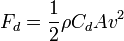 , works at all speeds. It is an exact equation. What happens is that the Drag Coefficient,
  changes depending on velocity, which causes the effects of drag being linearly dependant on velocity at low Reynolds numbers and drag being quadratically dependant on velocity at high reynolds numbers and a weird sort of schlooping at medium Reynolds numbers.
This picture explains it better than I can:

The x axis is Reynolds Number, the Y axis is Drag Coefficient.
I don't profess to be an expert on this point by any stretch of the imagination. However, I did find a drag calculator here for cylinders (ties are concpetually cylinders). Here is how it computes the for cylinders based on a Reynolds Number:
//
//Function to compute Cd for cylinder and a given Re
//Curve fit is to texts such as RC and GGH who appear to
//give different plots than other texts.
//
// The fit is as follows:
//      The MAE formula for RE<1
//      White's -2/3 power law curve fit for Re in [1,10^5]
//      A parabola (w/axis of symmetry at Re=10^5) from
//                 10^5 to 2.5*10^5
//      A constant=0.18 for Re between 2.5*10^5 to 6*10^5
//      Craig Lusk's 0.63 power law from 6*10^5 to 4*10^6
//      A constant 0.6 for Re>4*10^6
//
// Checks still ought to be made!!!!
//
var rdum="";
var sdum="";
function cd0(redum,sdum){

   var e_num = 0.577216;
   var at = Math.pow(10,5);

   var x1 = 1;
   var x15 = at;
   var x2  = 2.5*at;
   var x3  = 6*at;
   var x4  = 4*10*at;

   var y2=0.18;
   var y1=1.0;

   var alpha = (y2-y1)/Math.pow( x2-x15,2 );


   if(redum<=x1){
//     document.drag.debug1.value='In the Re < 1 block with Re='+r(redum,4)
     var t1 = Math.log(8/redum);
     var t2 = redum*( 0.5 - e_num + t1 );
     var cd = 8*pi/t2;
     }

   else if(x1<redum && redum<=x15){
//     document.drag.debug1.value='In the 10^5>Re>1 block with Re='+r(redum,4)
     var q1 = Math.pow(redum,2/3);
     var q2 = 10/q1;
     var cd = 1 + q2;
     }

   else if(x15<redum && redum<=x2){
//     document.drag.debug1.value='In the 2.5x10^5>Re>10^5 block with Re='+r(redum,4)
     var cd = alpha*Math.pow(redum-x15,2) + y1;
     }

   else if (x2<redum && redum<=x3){
//     document.drag.debug1.value='In the 6x10^5>Re>2.5x10^5 block with Re='+r(redum,4)
     var cd = 0.18;
     }
   else if (x3<redum && redum<=x4){
//     document.drag.debug1.value='In the 4x10^6>Re>6x10^5 block with Re='+r(redum,4)
     var s1 = redum/x3;
     var cd = 0.18*Math.pow(s1,0.63);
     }
   else if (x4<redum) {
 //     document.drag.debug1.value='In the Re>4x10^6 block with Re='+r(redum,4)
    var cd = 0.6;
     }
return cd;
}
//
Now, Reynolds number itself is based on fluid flow (ie: the instaneous velocity of the section of tie in question). Here's the function to compute the Reynolds Number, drag, etc. from the same source as before:
//
//Block to compute Re, Cd, and drag
//
function d_force(){
    var fchoice=document.drag.fluid.options[document.drag.fluid.selectedIndex].value;
    var uchoice=document.drag.units.options[document.drag.units.selectedIndex].value;
    var schoice=document.drag.shape.options[document.drag.shape.selectedIndex].value;
    if (schoice==0){
      var s="cylinder";
      }
    else {
     var s = "sphere";
      }

    var dia = document.drag.dentry.value;
    if (dia==""){
      alert('Hey!!!! You need to enter a diameter of the '+s+'. Please do so and click the calculate button again.');
      }
    var v   = document.drag.velocity.value;
    if (v==""){
      alert('Hey!!!! You need to enter the freestream velocity. Please do so and click the calculate button again.');
      }
    var re  = dia*v/( kv[fchoice]*kfactor[uchoice] )
    var den = dense();

    if (schoice==0){
      var cd = cd0(re);
      var drag = 0.5*den*v*v*cd*dia;
      var dunit = funit[uchoice]+funita[uchoice];
      }
    else {
      var cd = cd1(re);
      var af = pi*dia*dia/4;
      var drag = 0.5*den*v*v*cd*af;
      var dunit = funit[uchoice];
      }
    if (re>10000){
       document.drag.re.value=sci_not(re);
       }
    else {
        document.drag.re.value=r(re,ndigits);
      }
    document.drag.cd.value=r(cd,ndigits);
    if (drag<=0.001){
       document.drag.drag.value=sci_not(drag);
       }
    else {
       document.drag.drag.value=r(drag,ndigits);
       }
    document.drag.dunit.value=dunit;


}
Now, the java calculator returns units in drag per unit length. That's why I ended up integrating across the length of the tie...
Now, I can understand not wanting to be so precise if it involves alot of extra work. If I knew what was involved when I first started I proably would have just stuck with Laminar flow and be done with it. But I didn't, and the works all here.
Anyway, there you are ;)
--Numsgil 09:55, 8 May 2006 (MST)
- I'm aware of all this. But what you're describing only applies to a geometric shape (sphere or cylinder) placed in a uniform and constant flux. We definitely aren't in this situation in DB. With the bots constantly moving around in random directions, there's a lot of turbulence and you get all sorts of phenomena which affect the bots significantly, like wakes, stalls, etc. It's simply impossible to get a realistic simulation of hydrodynamics, because we'd need a (preferably adaptative) grid with step size smaller than the bots' size. I think you're fooled by having an accurate formula into thinking that it can describe DB physics accurately. Sprotiel 10:40, 8 May 2006 (MST)
- Right, I know that if I really wanted to simulate the fluid flows I'd be opening a whole can of worms really best not opened. But the transition from laminar to turbulent flows is something that is indeed simulatable, and I see no reason not to. --Numsgil 17:41, 8 May 2006 (MST)
- No, it's not, because it depends critically on having a reasonable model of the fluid flows. If the incoming flow is turbulent, it can't become laminar when it reaches the tie, even if the flow around the tie would be laminar if it were placed in a laminar flow. What you're proposing is just an arbitrary expression with little correspondence with physics - arbitrary for arbitrary, I'd prefer to use something as simple as possible. Another aspect of the problem I evoked on the forum is that in DB, relevant lengths differ only at most by an order of magnitude. If you look at the graph above, you'll notice that it doesn't have much structure on the scale of a decade, which means that using your formula won't induce any interesting behaviour. Sprotiel 07:39, 9 May 2006 (MST)
- I'm having a hard time understanding your notation (a somewhat ironic statement :P). Please tell me what sort of forces the following test cases provide:
- Right, I know that if I really wanted to simulate the fluid flows I'd be opening a whole can of worms really best not opened. But the transition from laminar to turbulent flows is something that is indeed simulatable, and I see no reason not to. --Numsgil 17:41, 8 May 2006 (MST)
- [A's cross velocity, B's cross velocity]: [x, y] s.t. x and y are elements in: {0, -13, 13} --Numsgil 18:28, 8 May 2006 (MST)
- I don't exactly understand your question, but I put the formulas for FB, the transverse force applied on B. wA and wB are the transverse velocities of the bots. I think you can compute what you want to know with this. Sprotiel 07:39, 9 May 2006 (MST)
- [A's cross velocity, B's cross velocity]: [x, y] s.t. x and y are elements in: {0, -13, 13} --Numsgil 18:28, 8 May 2006 (MST)